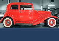
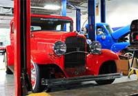
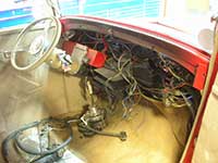
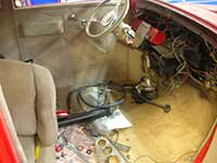
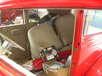
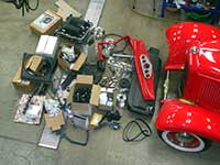
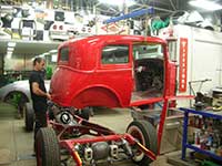
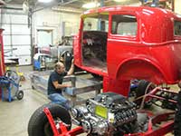
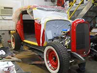
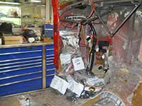
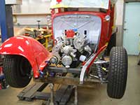
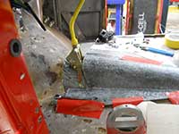
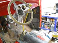
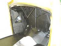
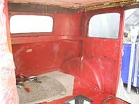
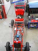
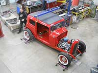
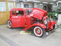
The two photos left and right are of an incoming 1932 Ford Victoria street rod that we are re-doing and updating for our customer. The four pictures at the bottom show the condition of the car when it was brought to us. It was in total disarray.
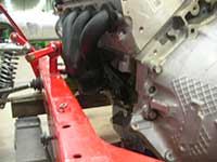
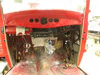
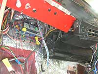
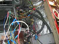
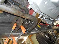
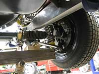
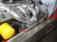
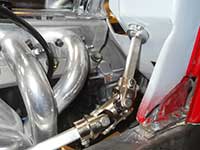
In this group of six photos the left and right ones show the body being removed from the chassis. The lower left photo shows how the previous builder couldn't figure out how to make the steering go around the headers. The next 3 photos show the amateurish fiberglass work and wiring.
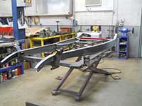
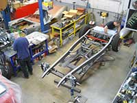
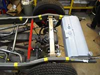
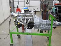
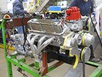
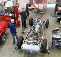
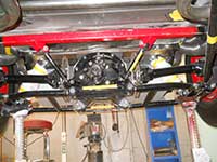
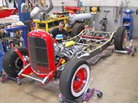
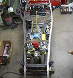
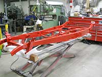
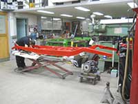
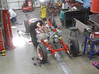
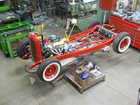
In this group of 6 photos the left and right photos show the new HEIDT'S reproduction of the 32 Ford chassis. The bottom left photo shows the fitting of the new gas tank to the new chassis. The middle 2 photos on the bottom show the new Ford engine. The last photo is Anthony and the owner going over the chassis details.
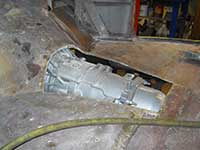
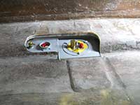
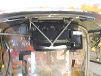
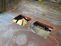
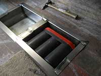
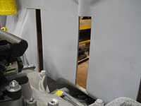
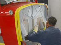
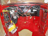
In this group the left picture shows the modifications to the firewall to accomodate the new engine. The photo right shows modifications to the fiberglass floor to accomodate the automatic transmission. The photo bottom left shows the access hole for the fuel pump that is cut in the floor of the body. The next shows mocking up of the power brake mounting bracket. The last 2 photos show mocking up of the various chassis details.
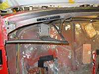
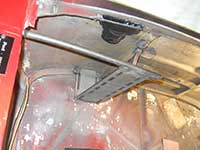
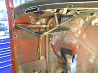
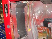
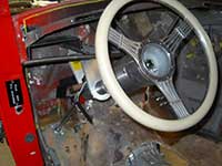
In this group the left and right photos show two different views of before and after of cutting in the defroster vents. The photo bottom left shows where the defroster heat will exit the dashboard. The last 3 photos show the new steering column mounting bracket.
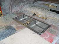
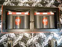
In this group of 6 photos the left shows the mounting plate installed in the right kick panel for the fuse panel. The right photo shows mocking up of the heater and air conditioning. The photo bottom left shows the fuse panel and wiring temporarily hung in place. The last 3 photos show the location and mounting of the batteries in the rear passenger floor.
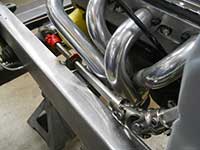
This group left and right show modifications made to the firewall and a close up of the same. The 4 bottom photos show how we accomplished getting the steering around the headers.
In this group of 6 photos the left and right show fabrication of the transmission tunnel. The bottom 2 left show mocking up of the new chassis and engine. The last 2 show Joe fiberglassing the firewall modifications.
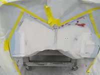
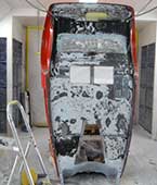
The photo left shows the firewall in primer. The photo right shows the transmission tunnel in epoxy primer. The bottom left 2 photos show the inside of the body in epoxy primer. The last 2 photos show modifications to the dashboard to accomodate the heating and air conditioning controls.
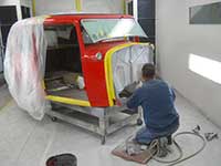
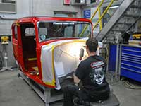
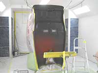
The photos left and right show Anthony preparing the firewall for painting and the new wiring harness with the accessible fuse panel and heating and air conditioning unit. The bottom 4 photos show the assembly of the chassis.
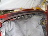
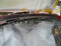
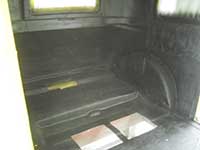
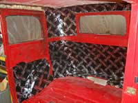
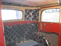
The photo left shows the inside of the body before the application of dynamat and the photo right shows the dynamat being installed. The 4 photos below show the underside of the body being prepared for undercoating and the chassis and body being prepped to put together and then installed.
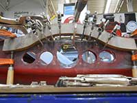
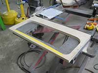
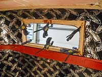
The photo left shows the car being re-assembled. The photo right shows the wood grained dash being assembled prior to installation. The photos below, left to right, show two 6 volt Optima batteries located in the rear floor area, construction of the wood frame surrounding the rear window, the wood frame bonded and installed in the body and all the wood framing around the rear windows.
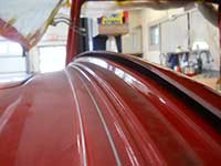
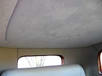
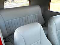
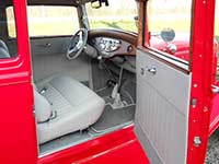
These last five photos show the car, interior and exterior finished. The leather was Austrian Dovegray. The carpet is English Wilton Wool bound in matching leather.